前回、Ultra96-V2上でPYNQ環境を使える状態となりましたが、用意されているオーバーレイ(FPGAデザイン)はボード上のLED点灯制御もできませんでした。 今回はボード上のLEDの点灯制御を行うオーバーレイを作ってみたいと思います。
主にXilinxのハードウェア設計ツールVivado上での作業となります。 使用したバージョンは2020.02となります。
執筆者 : 原田 秀一
Ultra96-V2のLED
Ultra96-V2ボード上にはいくつかのLEDがあり、以下のマニュアルの 5.9 LEDs に記載されています。
Ultra96-V2 Hardware User's Guide
LEDには電源状態やコンフィグレーション完了を示すなど固定の役割のものもありますが、User-controllableの記載があるものは任意に制御可能です。
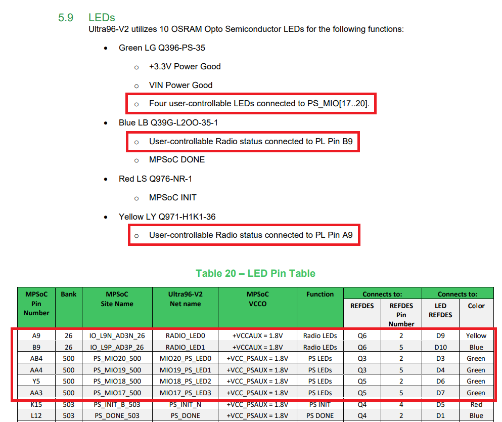
LEDの接続先はPS_MIO[17..20]とPL Pin B9, PL Pin A9と記載されています。このPS, PLの部分は接続先のZynq内部ブロックが異なることを表しています。
PSとPL
ZynqではArmコアを含むプロセッサ周辺ブロックをProcessing System(PS)、FGPAブロックをProgrammable Logic(PL)と呼んでいます。 上記LEDのPS_MIOはProcessing System(Armコア部分)のMIO(Multiplexed I/O)への接続、PLはProgrammable Logic(FPGA部分)への接続を意味します。
PS_MIOに接続されたLEDはFPGAを介さずにCPUからGPIOなどのペリフェラルから制御可能、PLに接続されたLEDはFPGAに実装した回路から制御可能となります。 また、PLはPSから制御可能なので、FPGA上にGPIO回路を実装し、CPUからそのGPIOを制御できます。
今回は、このFPGA上にGPIOを追加し、PLに接続されているLEDを制御するPYNQオーバーレイを作成します。
Vivadoでの開発作業
ここからはハードウェア開発環境Vivadoを使ってFPGAの設計を行いビットストリームを作成します。 以下の流れで作業します。
プロジェクト作成
対象ボード(FPGAデバイス)の指定等を行います。
制約ファイル設定
主にFPGAのピンアサインを行います。
IPインテグレーターでの作業
IP (Intellectual Property, FPGAでは回路のライブラリのようなもの) を配置、設定、接続し回路設計を行います。
HDLラッパー作成
IPインテグレーターで作成した回路を使うために必要なラッパーファイルを作成します。
ビットストリーム作成
設計した回路をFPGAに書き込むためのビットストリームを作成します。
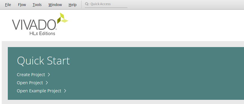
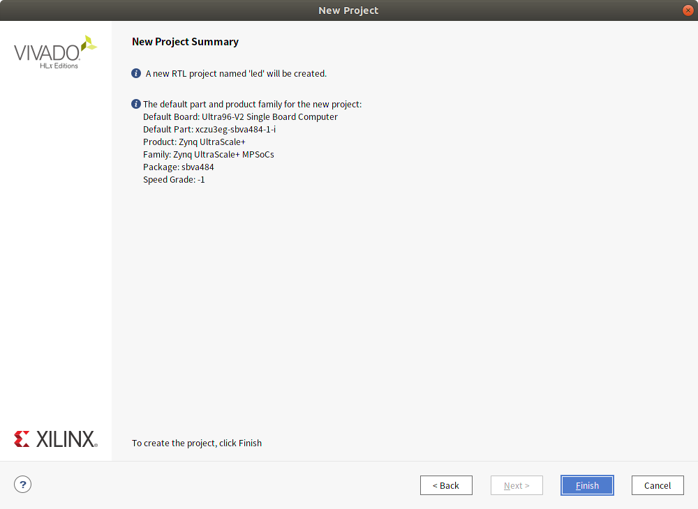
プロジェクト作成
Quick StartからCreate Projectを選択します。
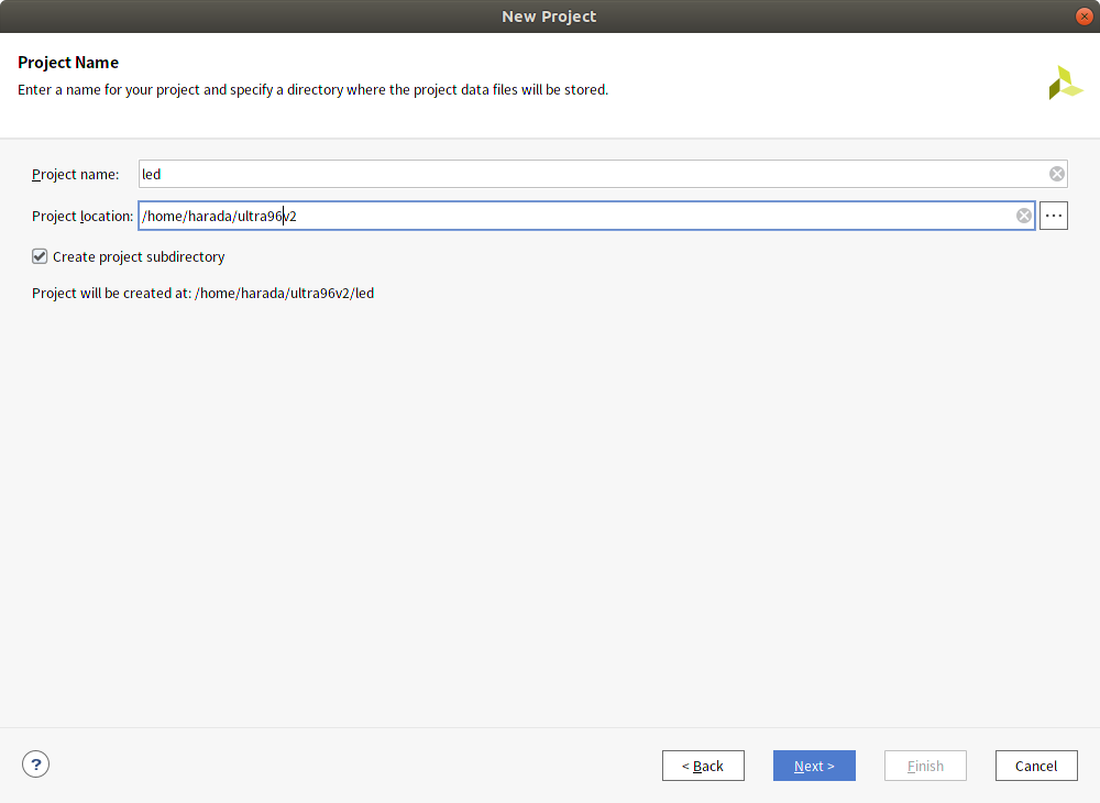
今回はproject名をled, ディレクトリはhome以下のultra96v2を指定しました。
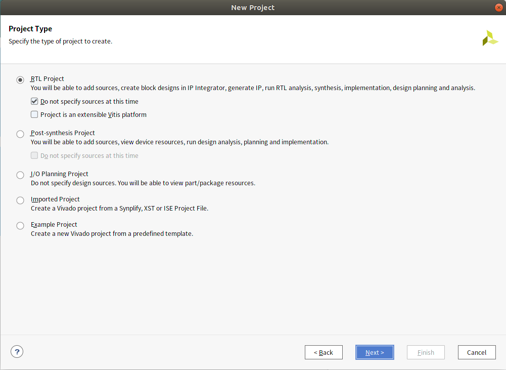
project typeはRTLを選択します。
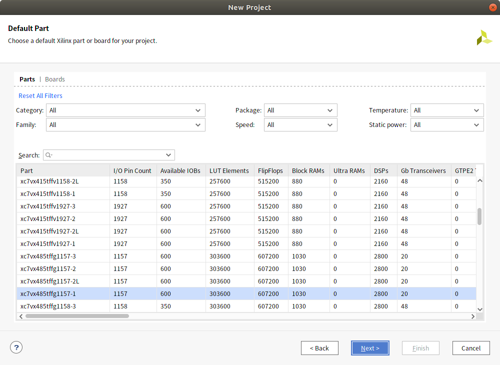
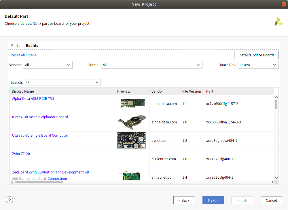
Default Part画面ではPartsタブからBoardsタブに切り替えて一覧からUltra96-V2を選択します。
ボードファイルのインストール
一覧に対象のボードがない場合、ボードファイルのインストールが必要です。 初期状態ではUltra96-V2のボードファイルは含まれていないため、ダイアログ右上のInstall/Update Boardsを選択し、XHub Storesの画面からボードを選択して右クリックし、installを実行します。
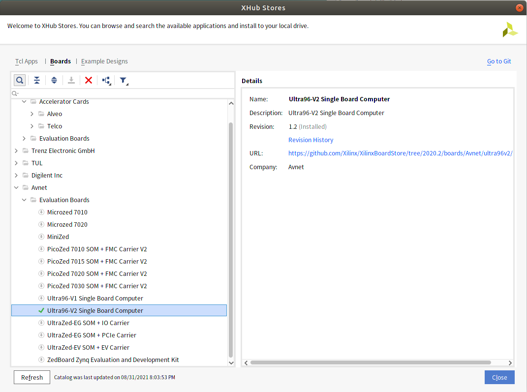
XHub Stores
選択したボードが反映されているか確認してFinishを押して終了します。
私の環境ではバグなのか選択したボードの内容が反映されていないことがあり、Vivadoを再起動して作業しなおして反映されました。
制約ファイル設定
制約ファイル(拡張子xdc)は、入出力ポートの端子へのアサイン、端子の信号レベル設定、タイミングに関する制約等を設定するファイルです。 記述内容はTcl形式となります。
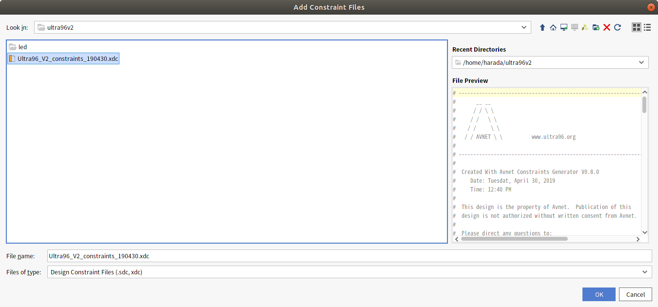
今回はAvnet提供の制約ファイルを使用します。
Ultra96-V2 | Avnet Boards のTechnical Documents中のConstraints Ultra96-V2 Constraints Rev 1 です。
ダウンロードしたファイルを解凍してUltra96_V2_constraints_190430.xdcを展開しておきます。
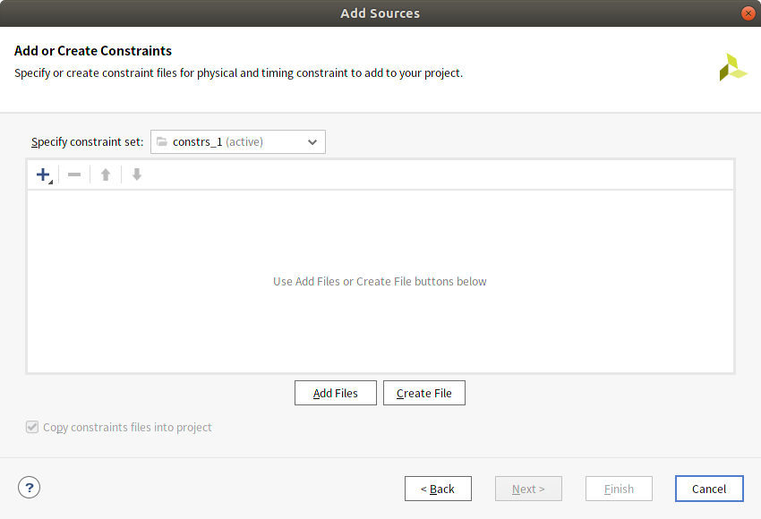
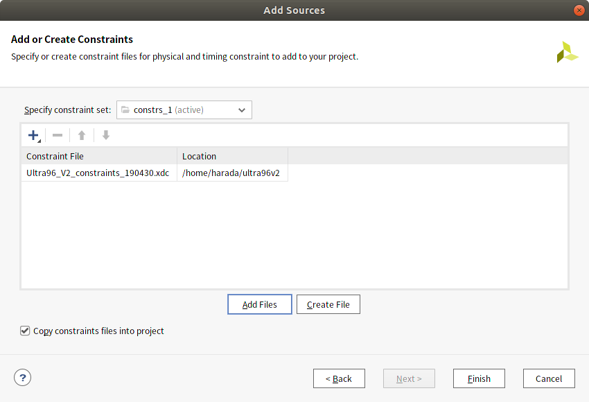
プロジェクトに制約ファイルを追加します。
Flow Navigator - PROJECT MANAGER - Add Sourcesを選択します。
Add or create constraintsを選択します。
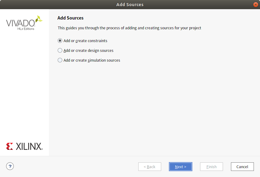
Ultra96-V2用の制約ファイルを追加します。
追加した制約ファイルを開くとA9= RADIO_LED0, B9 = RADIO_LED1 として定義されていることが確認できます。
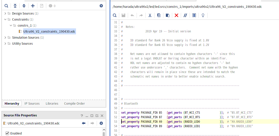
制約ファイル抜粋
# ----------------------------------------------------------------------------
# Bluetooth
# ----------------------------------------------------------------------------
set_property PACKAGE_PIN B5   [get_ports {BT_HCI_CTS             }];  # "B5.BT_HCI_CTS"
set_property PACKAGE_PIN B7   [get_ports {BT_HCI_RTS             }];  # "B7.BT_HCI_RTS"
set_property PACKAGE_PIN A9   [get_ports {RADIO_LED0             }];  # "A9.RADIO_LED0"
set_property PACKAGE_PIN B9   [get_ports {RADIO_LED1             }];  # "B9.RADIO_LED1"
IPインテグレーターでの作業
IPインテグレーターでは回路図CADのようにIPを配置してポート間の信号接続を行うことができます。 今回はZynq PSとGPIOのIPを配置、接続しGPIO出力をボード上のLEDに接続します。
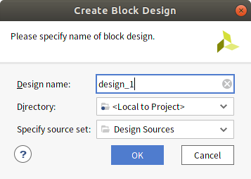
Flow Navigator - IP INTEGRATOR - Create Block Designを選択します。
デザイン名はデフォルトのままとします。
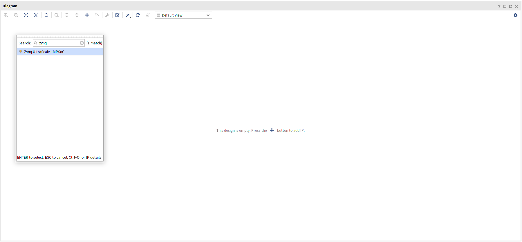
空のDiagramが開きます。
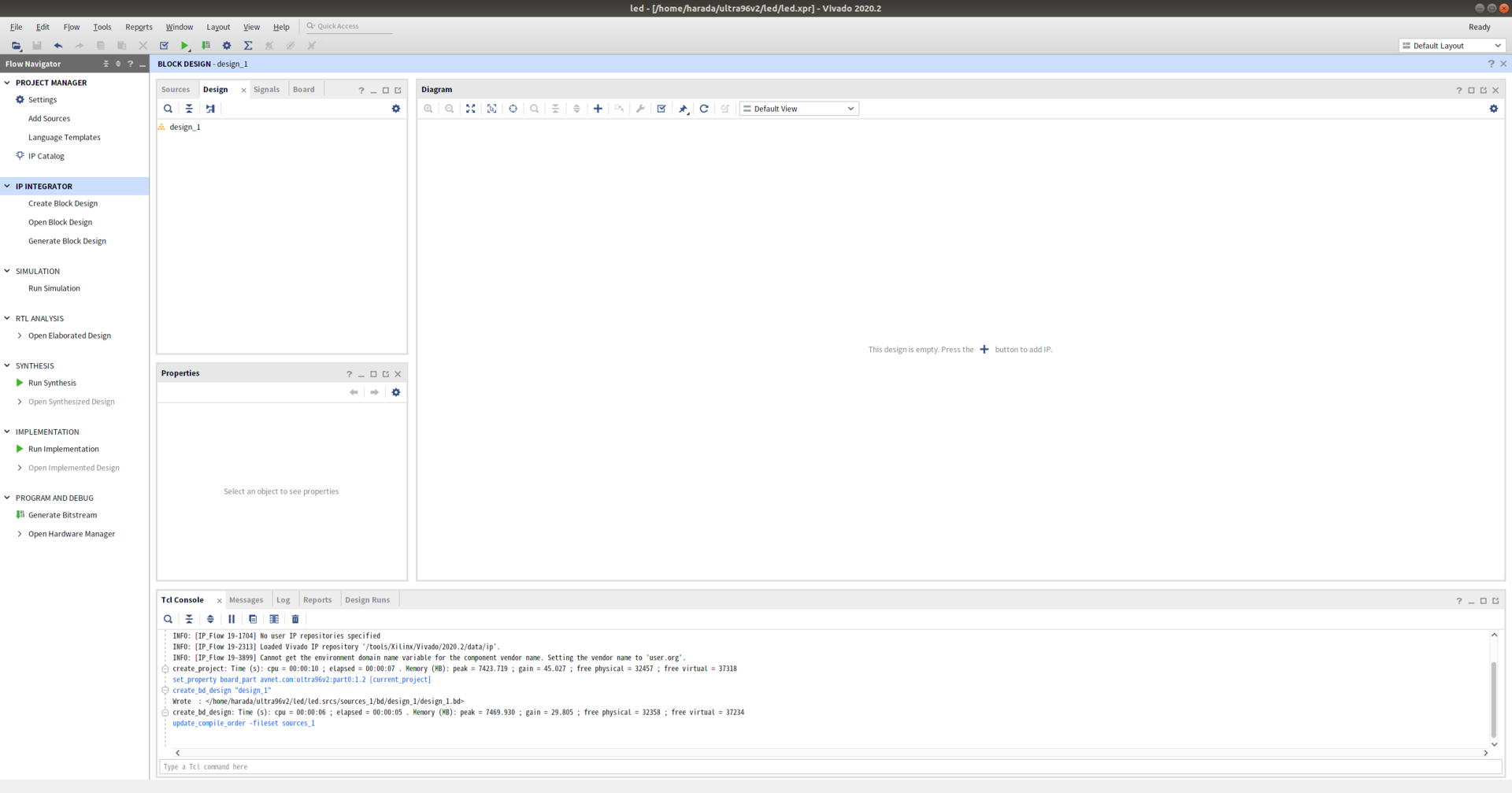
Diagramウィンドウの中央、または上部の + ボタンを押してIPを追加します。 まずZynq UltraScale+ MPSoCを追加します。
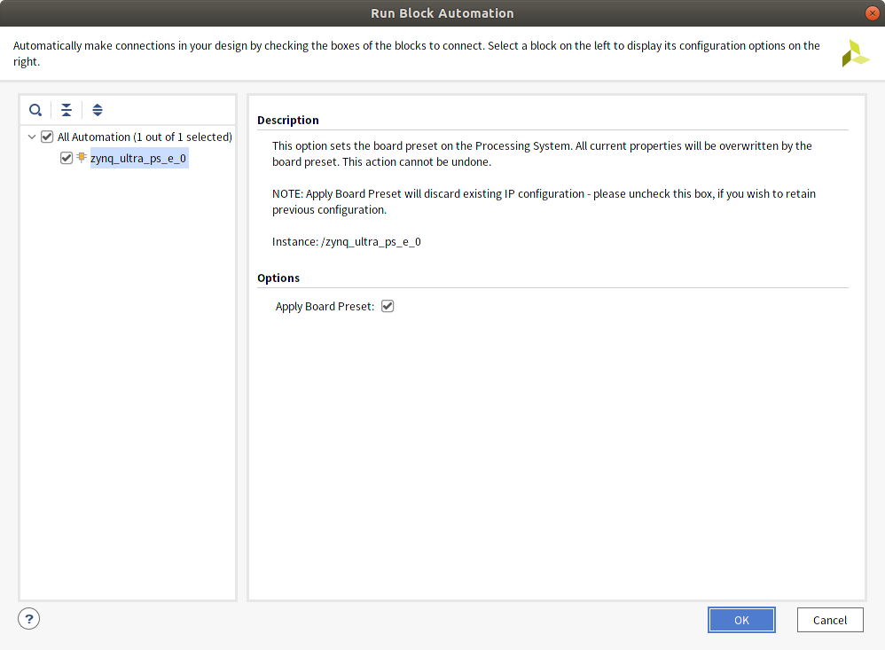
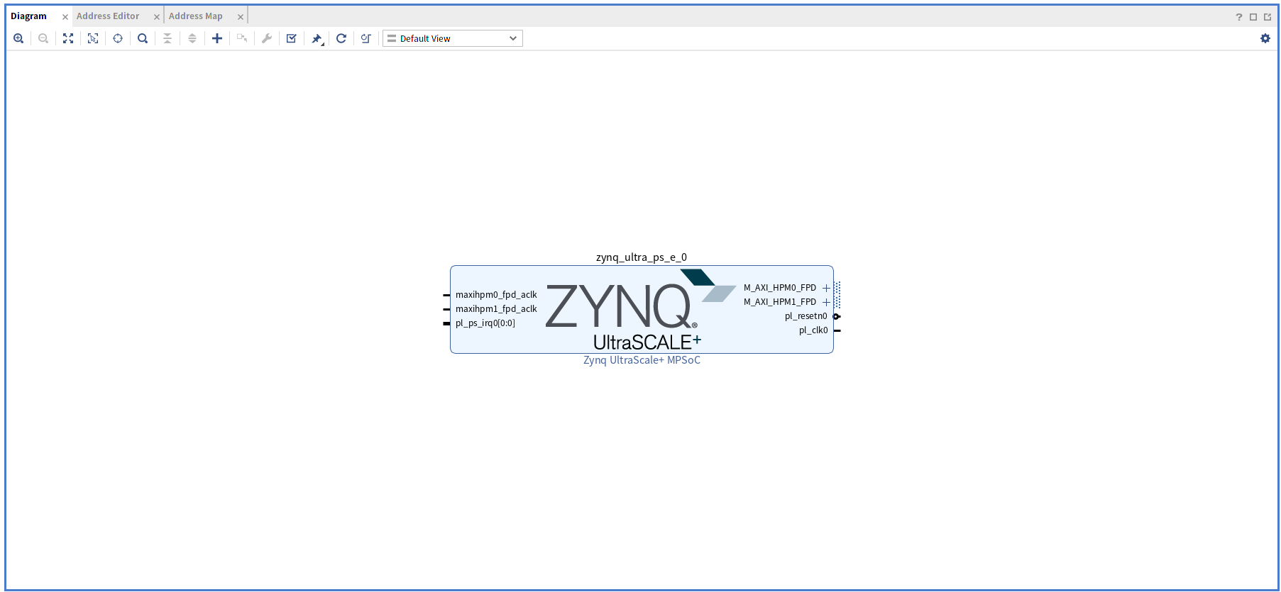
追加後、上部に表示されるRun Block Automationを実行します。
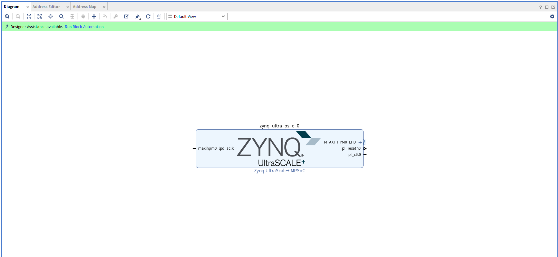
デフォルトのままでOK
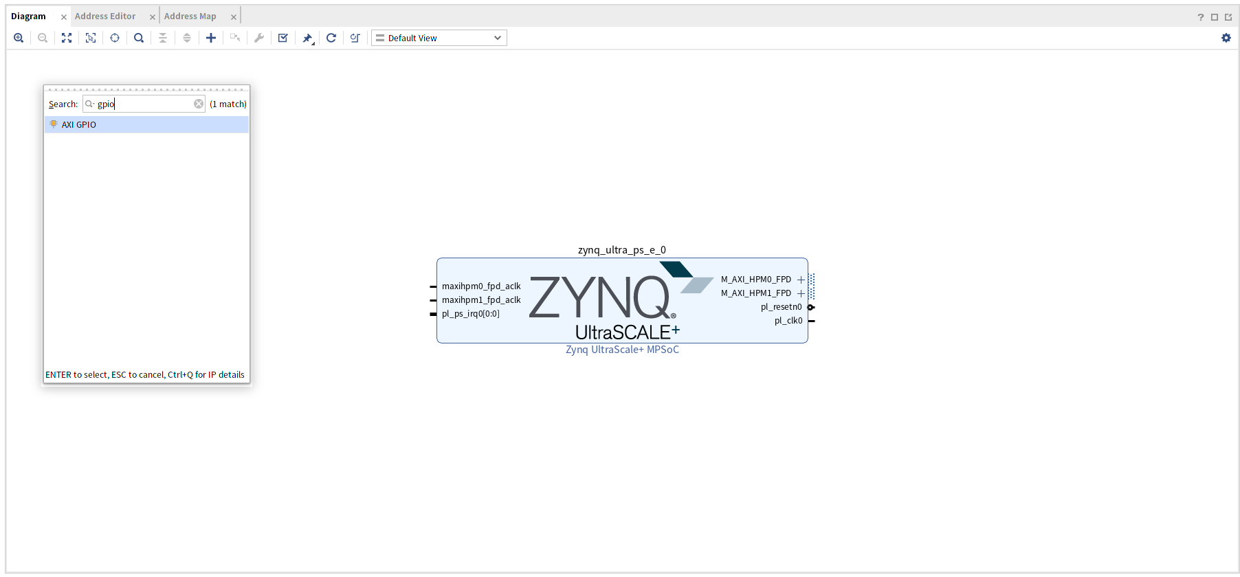
次にGPIOを追加します。 画面上部 + ボタンを押して AXI GPIOを追加します。
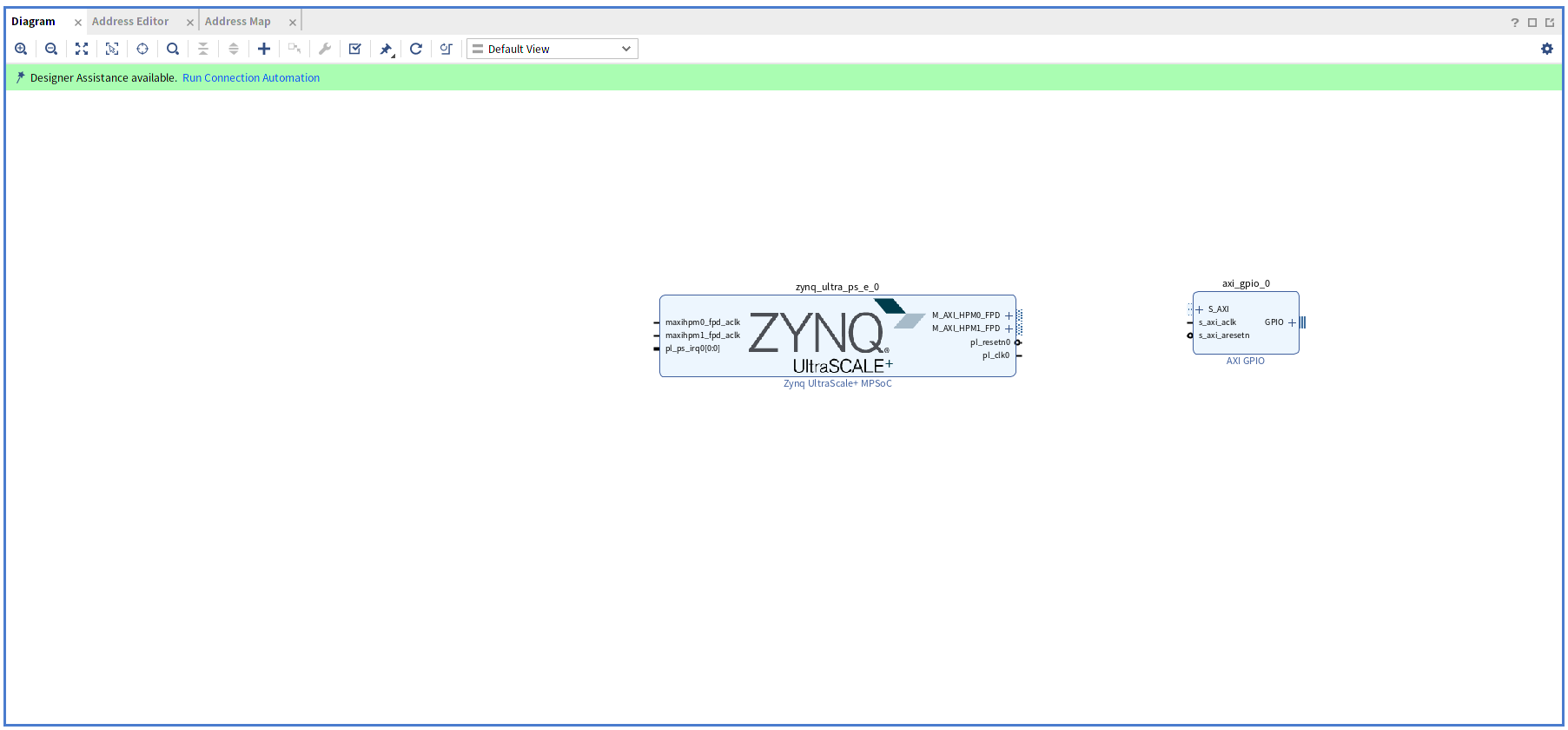
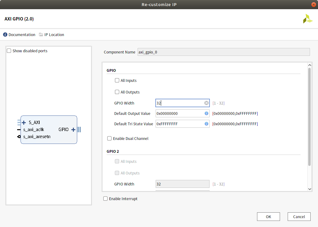
追加されたaxi_gpio_0をダブルクリックしてIPの設定を開きます。
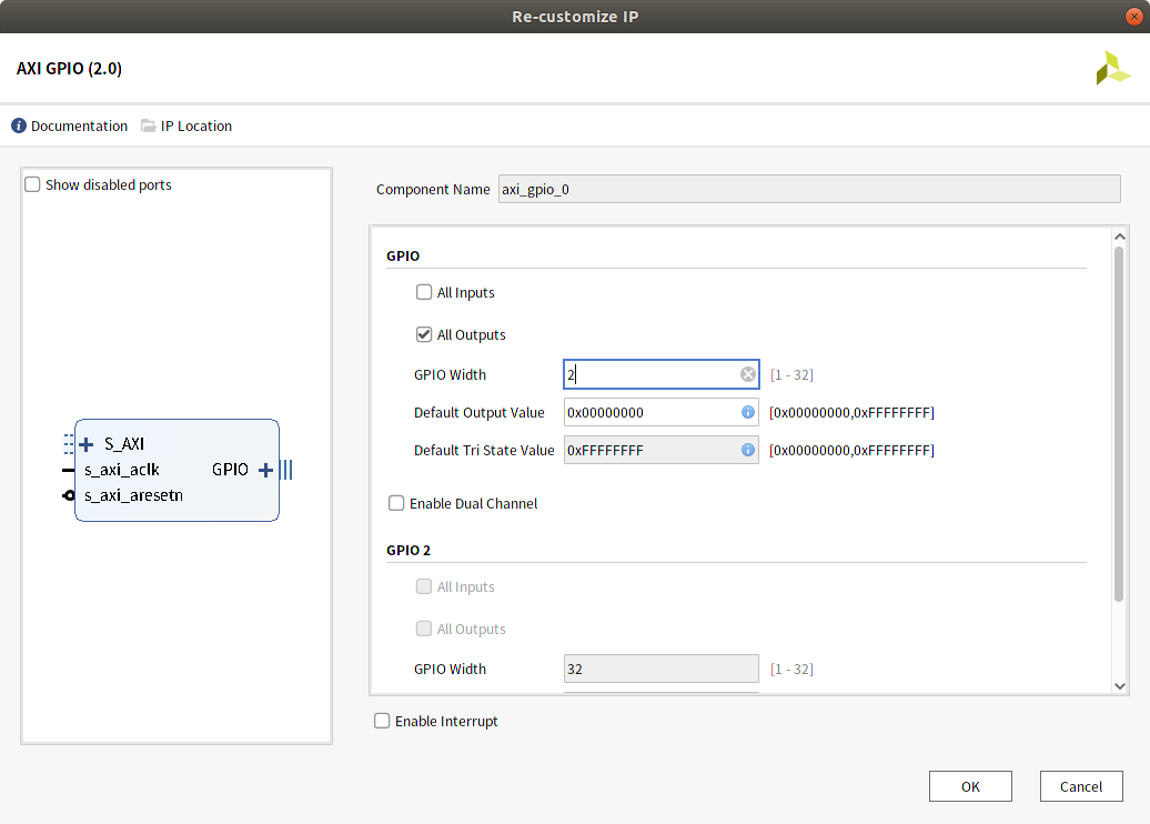
ここではLEDへの信号は2本だけなのでWidthを2, All outputに変更します。
Run Connection Automationで接続します。
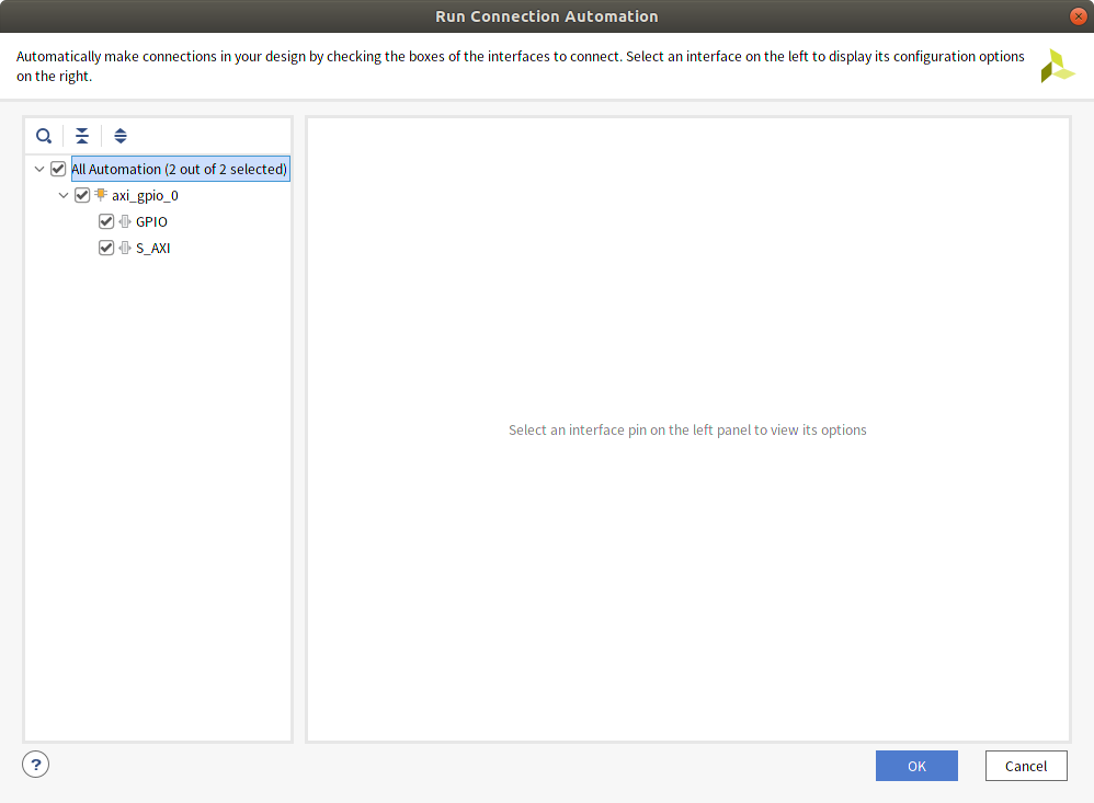
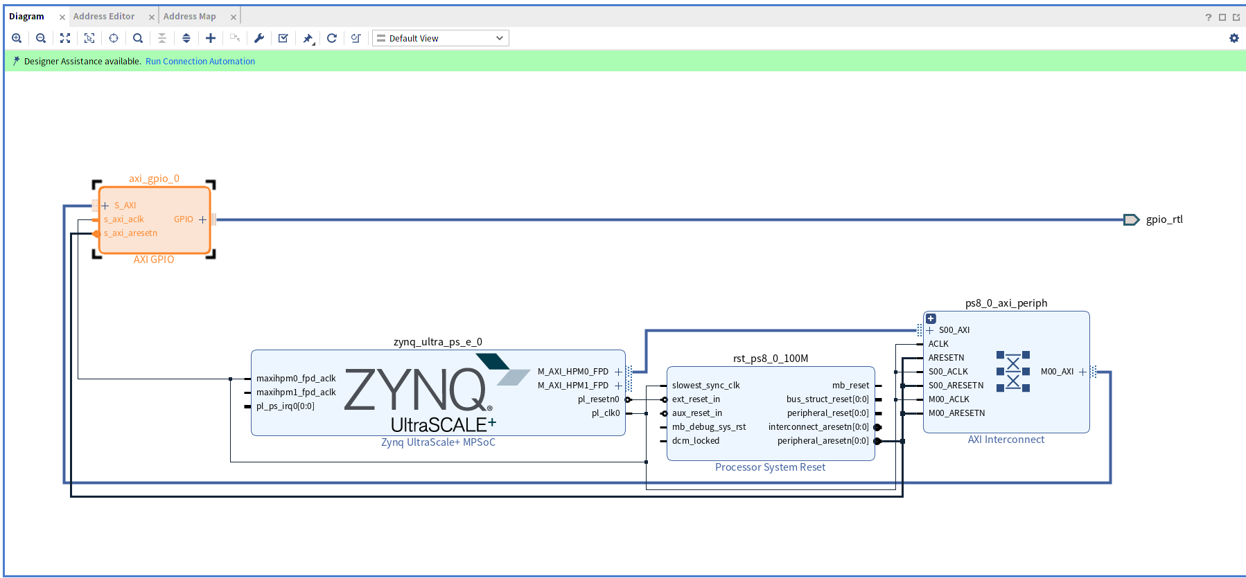
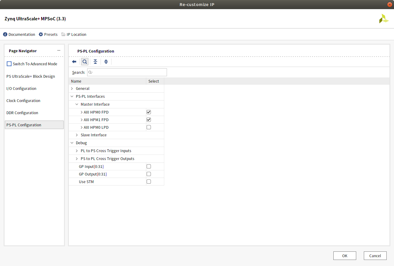
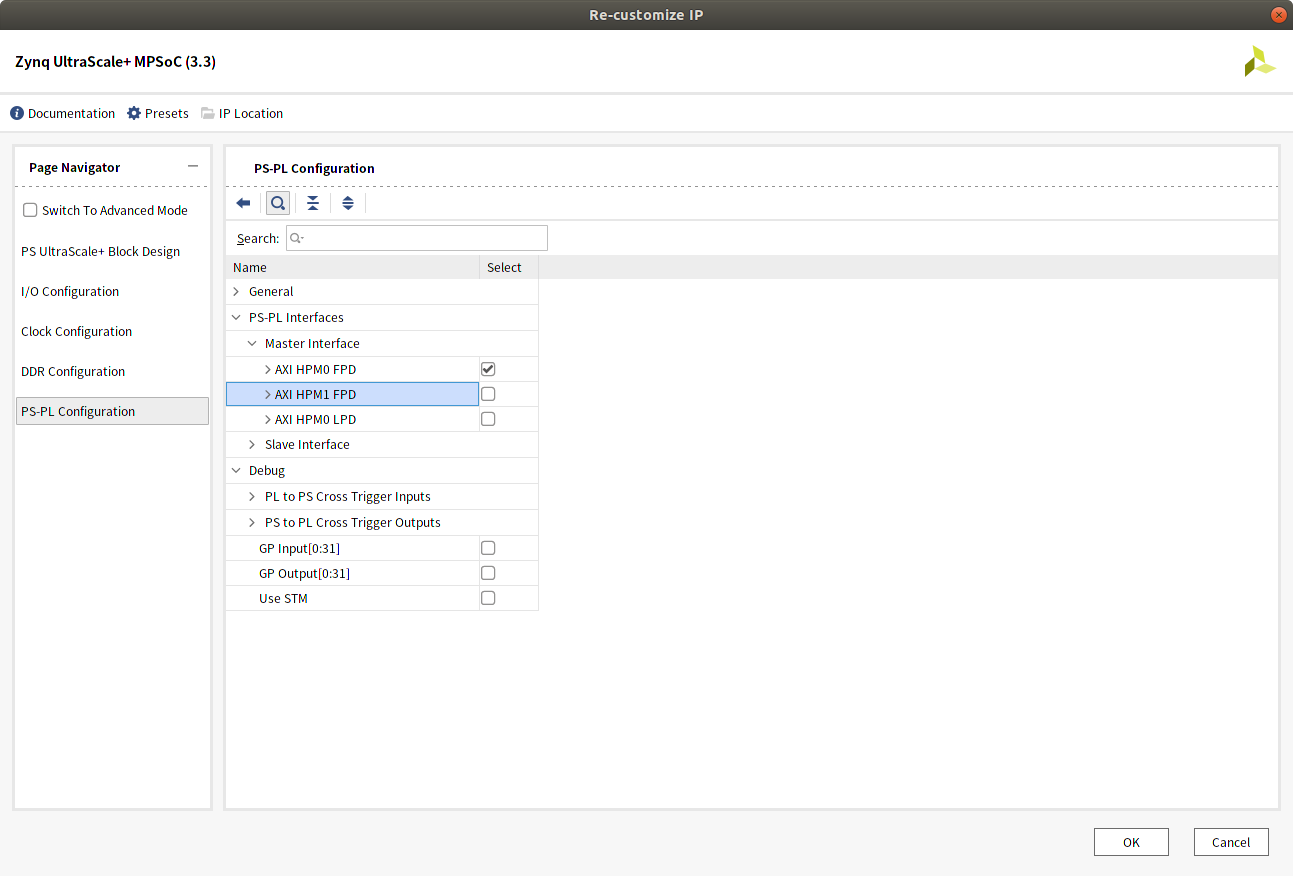
まだZynq IP部のAXI HPM1 FPDは未接続状態になっているため、Run Connection Automationの表示があります。 このインターフェースは使用しないのでZynq IP設定のPS-PL間のインターフェース設定からチェックを外して消しておきます。
GPIOからの信号をLEDに接続します。
GPIOからは2bit幅の出力となっていますが、1bitずつの信号として扱えるようにするためSlice IPを2つ追加します(LED2つ分の1bit x 2)。
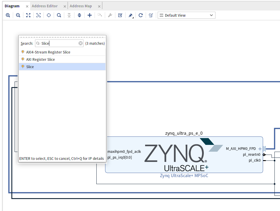
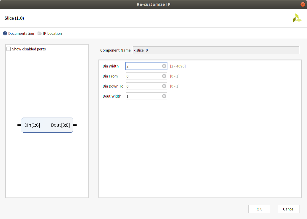
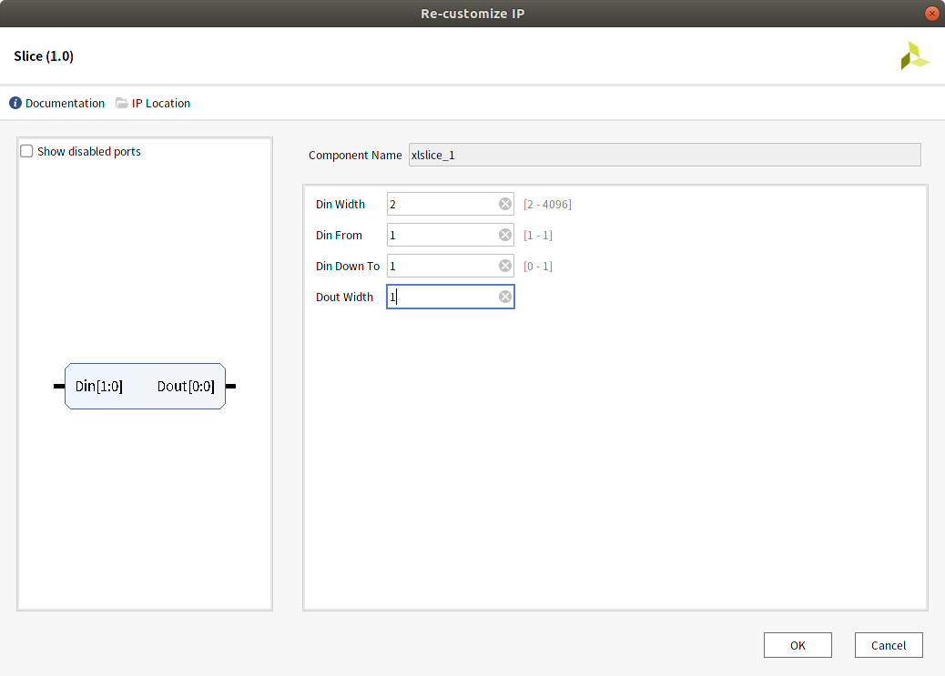
Slice IPの設定でDin Widthを2、Dout Widthを1に設定します。 Din From、Din Down Toは、2つのIPそれぞれ0,0と1, 1に設定します(どのビット位置を出力するかの設定)。
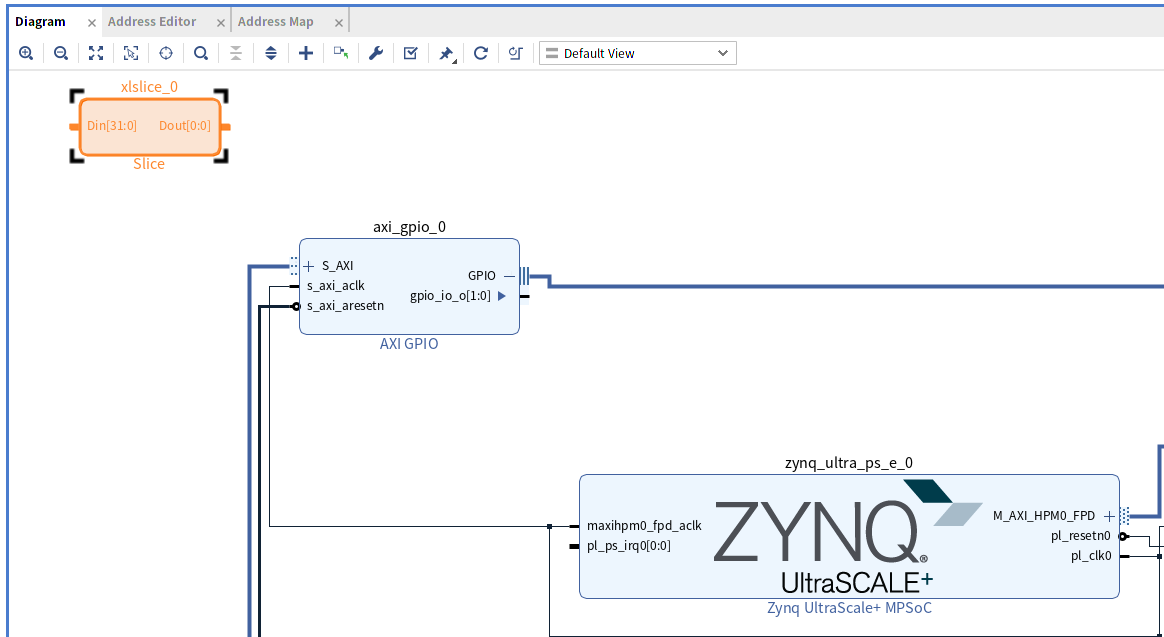
axi_gpio_0のGPIO + の部分を押してインターフェースを展開し、表示されたgpio_io_o[1:0]からSlice IPのDin[1:0]に接続します。
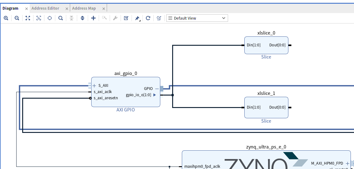
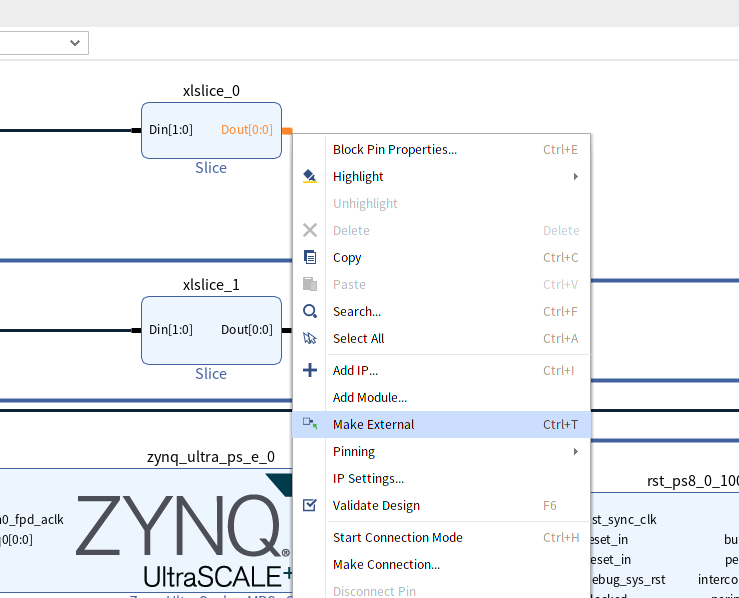
2つのSlice IPのDoutから右クリックメニューのMakeExternalで外部ポートを作成します。
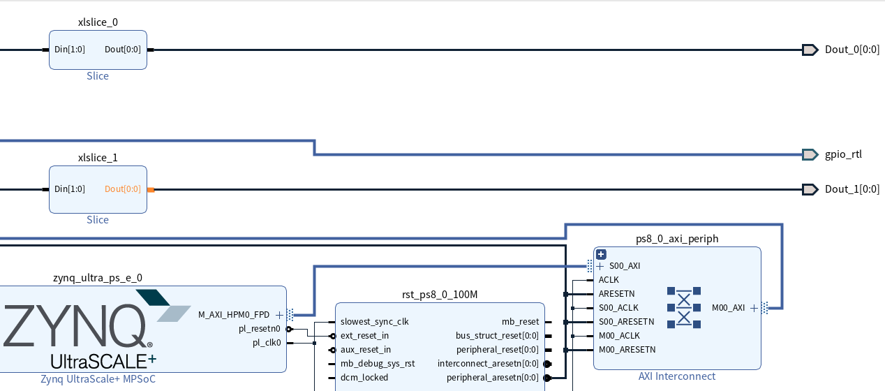
作成された外部ポートを選択してプロパティから名前を変更し、制約ファイルに定義されているポート名と一致させます。
ここではDout_0をRADIO_LED0, Dout_1をRADIO_LED1に変更します。
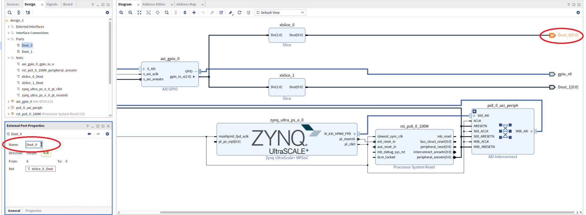
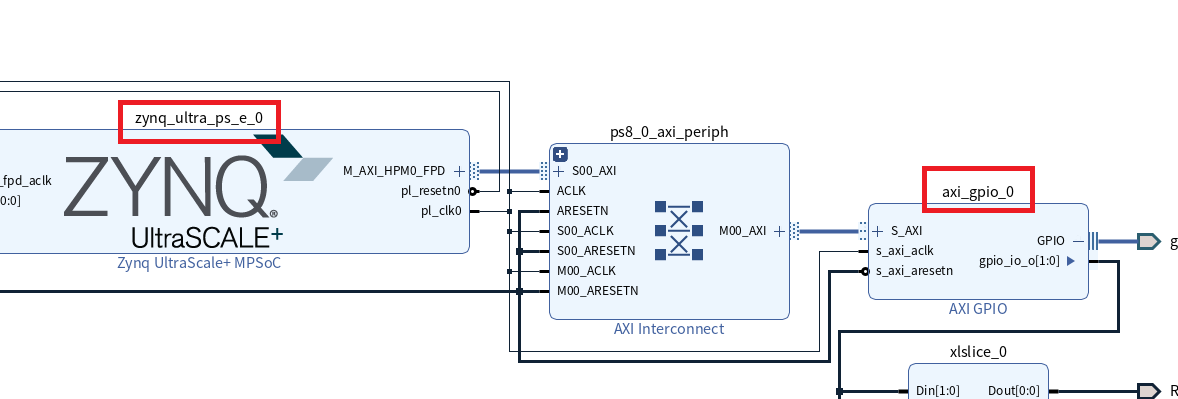
Diagram画面の右クリックメニューからRegenerate Layoutで整理し、以下のような全体図となります。
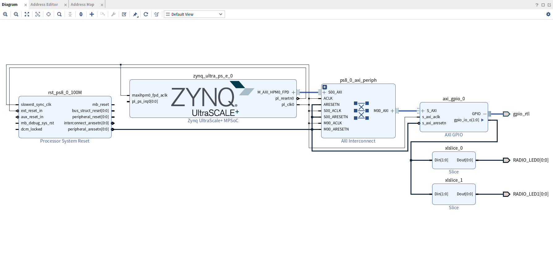
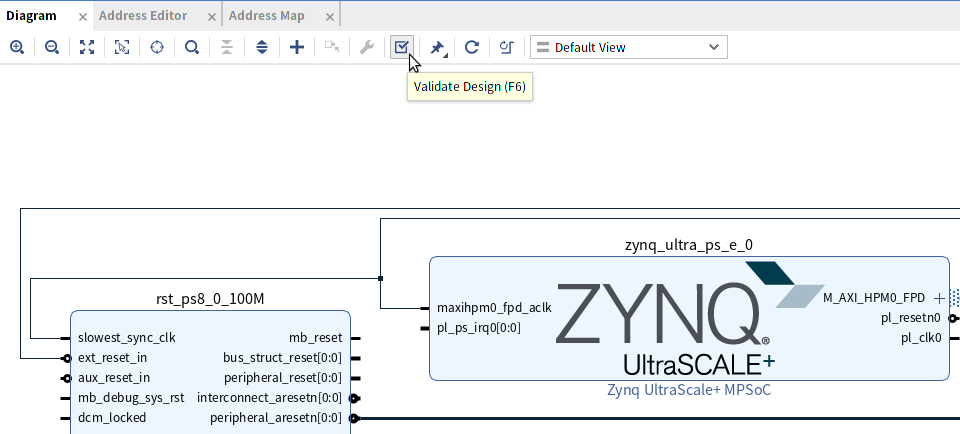
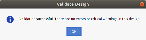
Validate Designで問題がないかチェックしておきます。
制約ファイルを変更してLEDに接続する例
上記では制約ファイルの定義に合わせてボードデザインを作成してLEDに接続しましたが、制約ファイルの定義を変更しボードデザインに合わせて接続することもできます。 これはGPIOからの出力を外部ポート名LEDとして定義した場合、以下のように制約ファイルを変更することで可能です。 この場合、Slice IPを使う必要がなくなり、手間が減ります。
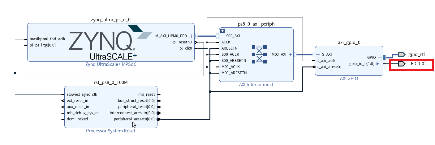
#set_property PACKAGE_PIN A9   [get_ports {RADIO_LED0             }];  # "A9.RADIO_LED0"
#set_property PACKAGE_PIN B9   [get_ports {RADIO_LED1             }];  # "B9.RADIO_LED1"
set_property PACKAGE_PIN A9   [get_ports {LED[0]             }];  # "A9.RADIO_LED0"
set_property PACKAGE_PIN B9   [get_ports {LED[1]             }];  # "B9.RADIO_LED1"
HDLラッパー作成
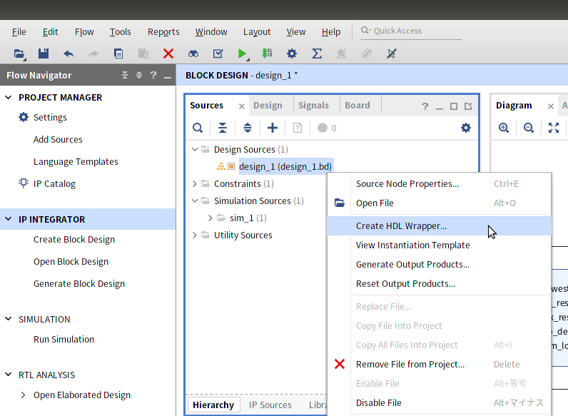
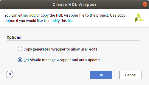
ボードデザイン(拡張子bd)ができましたがこれを使うためにはHDLラッパーの作成という手順が必要です。 Sourcesからdesign_1を選択し、右クリックメニューからCreate HDL Wrapperを実行します。
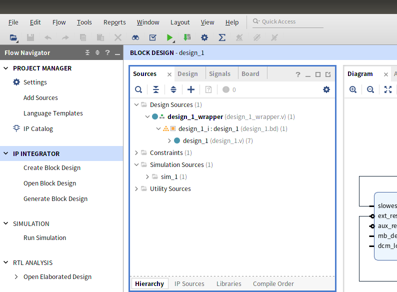
design_1_wrapper.vが生成されます。
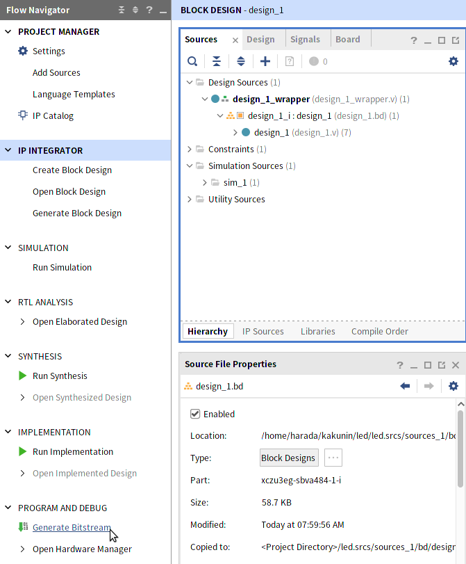
ビットストリーム作成
PROGRAM AND DEBUG から Generate Bitstreamを実行し、ビットストリーム(拡張子bit)を作成します。
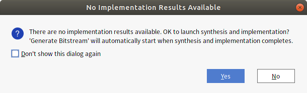
ここまで論理合成、配置配線を行っていないので確認ダイアログが表示されます。
Yesを押して進めればこのタイミングで実行されます。
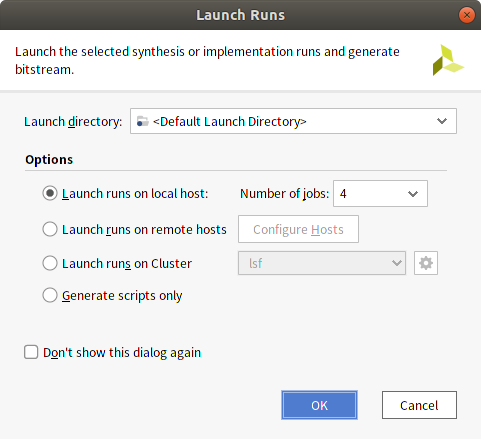
Launch RunsもデフォルトのままOKでビットストリーム作成が開始されます。
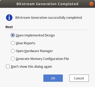
エラーがなければしばらくしてビットストリームができあがります。
このとき配置配線の結果を開くなどの選択が表示されますが、ここではキャンセルで終了します。
Vivadoでの作業はここで終了です。
PYNQ上で動作確認
Ultra96-V2のPYNQ環境でできあがったオーバーレイ(FPGAデザイン)を動かしてみます。
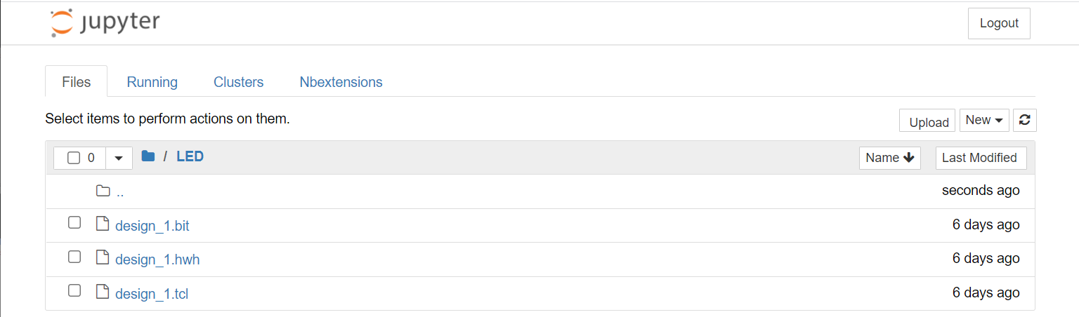
作業用にLEDディレクトリを作成しておきます。
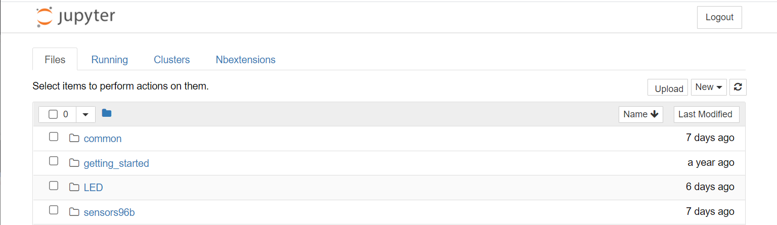
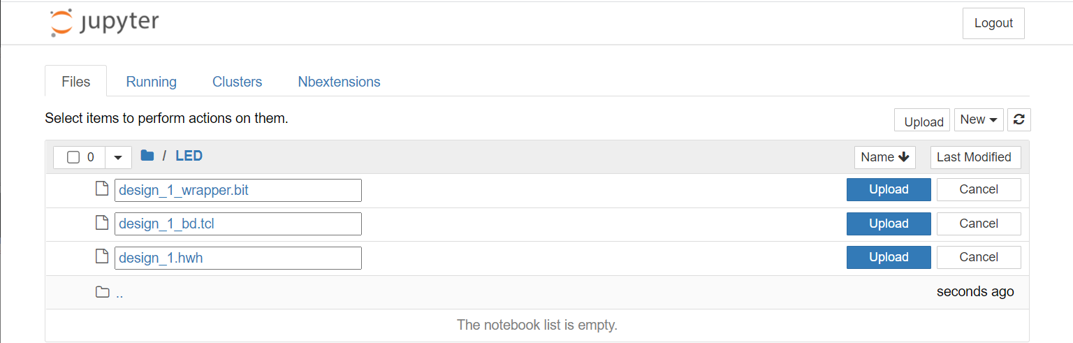
ファイル転送
UploadからPYNQ上にファイルを転送します。
対象はVivadoプロジェクトディレクトリled内の以下のファイルです。
led/led.gen/sources_1/bd/design_1/hw_handoff/design_1.hwh
led/led.gen/sources_1/bd/design_1/hw_handoff/design_1_bd.tcl
led/led.runs/impl_1/design_1_wrapper.bit
テスト実行
NewからPython3を選択してノートを作成します。 (以下はLED Testにリネームしています)
セルに以下のPythonコードを記述します。
from pynq import Overlay
import time

ol = Overlay('design_1.bit')

for i in range(10) :
    ol.axi_gpio_0.write(0,(i & 3))
    time.sleep(1)
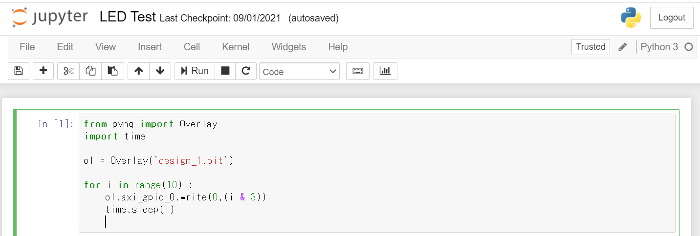
このセルを実行すると2個のLEDが点滅します。
PYNQからのFPGA制御詳細
from pynq import Overlay

ol = Overlay('design_1.bit')
ビットストリームを指定してOverlayクラスのインスタンスを作成します。
メモリマップされているIPを以下のようにして表示できます。
 for key in ol.ip_dict :
    print(key)
実行結果
axi_gpio_0
zynq_ultra_ps_e_0
これらの識別名は、Vivadoで作成したブロックデザイン中の各IPインスタンスの名前に対応します。
helpを使って確認するとread(), write()といったメソッドを持つことがわかります。
help(ol.axi_gpio_0)
help実行結果(クリックで展開)
Help on AxiGPIO in module pynq.lib.axigpio object:

class AxiGPIO(pynq.overlay.DefaultIP)
 |  Class for interacting with the AXI GPIO IP block.
 |
 |  This class exposes the two banks of GPIO as the `channel1` and
 |  `channel2` attributes. Each channel can have the direction and
 |  the number of wires specified.
 |
 |  The wires in the channel can be accessed from the channel using
 |  slice notation - all slices must have a stride of 1. Input wires
 |  can be `read` and output wires can be written to, toggled, or
 |  turned off or on. InOut channels combine the functionality of
 |  input and output channels. The tristate of the pin is determined
 |  by whether the pin was last read or written.
 |
 |  Method resolution order:
 |      AxiGPIO
 |      pynq.overlay.DefaultIP
 |      builtins.object
 |
 |  Methods defined here:
 |
 |  __getitem__(self, idx)
 |
 |  __init__(self, description)
 |      Initialize self.  See help(type(self)) for accurate signature.
 |
 |  setdirection(self, direction, channel=1)
 |      Sets the direction of a channel in the controller
 |
 |      Must be one of AxiGPIO.{Input, Output, InOut} or the string
 |      'in', 'out' or 'inout'
 |
 |  setlength(self, length, channel=1)
 |      Sets the length of a channel in the controller
 |
 |  ----------------------------------------------------------------------
 |  Data and other attributes defined here:
 |
 |  Channel = <class 'pynq.lib.axigpio.AxiGPIO.Channel'>
 |      Class representing a single channel of the GPIO controller.
 |
 |      Wires are and bundles of wires can be accessed using array notation
 |      with the methods on the wires determined by the type of the channel::
 |
 |          input_channel[0].read()
 |          output_channel[1:3].on()
 |
 |      This class instantiated not used directly, instead accessed through
 |      the `AxiGPIO` classes attributes. This class exposes the wires
 |      connected to the channel as an array or elements. Slices of the
 |      array can be assigned simultaneously.
 |
 |  InOut = <class 'pynq.lib.axigpio.AxiGPIO.InOut'>
 |      Class representing wires in an inout channel.
 |
 |      This class should be passed to `setdirection` to indicate the
 |      channel should be used for both input and output. It should not
 |      be used directly.
 |
 |  Input = <class 'pynq.lib.axigpio.AxiGPIO.Input'>
 |      Class representing wires in an input channel.
 |
 |      This class should be passed to `setdirection` to indicate the
 |      channel should be used for input only. It should not be used
 |      directly.
 |
 |  Output = <class 'pynq.lib.axigpio.AxiGPIO.Output'>
 |      Class representing wires in an output channel.
 |
 |      This class should be passed to `setdirection` to indicate the
 |      channel should be used for output only. It should not be used
 |      directly.
 |
 |  bindto = ['xilinx.com:ip:axi_gpio:2.0']
 |
 |  ----------------------------------------------------------------------
 |  Methods inherited from pynq.overlay.DefaultIP:
 |
 |  call(self, *args, **kwargs)
 |
 |  read(self, offset=0)
 |      Read from the MMIO device
 |
 |      Parameters
 |      ----------
 |      offset : int
 |          Address to read
 |
 |  start(self, *args, **kwargs)
 |      Start the accelerator
 |
 |      This function will configure the accelerator with the provided
 |      arguments and start the accelerator. Use the `wait` function to
 |      determine when execution has finished. Note that buffers should be
 |      flushed prior to starting the accelerator and any result buffers
 |      will need to be invalidated afterwards.
 |
 |      For details on the function's signature use the `signature` property.
 |      The type annotations provide the C types that the accelerator
 |      operates on. Any pointer types should be passed as `ContiguousArray`
 |      objects created from the `pynq.Xlnk` class. Scalars should be passed
 |      as a compatible python type as used by the `struct` library.
 |
 |  start_ert(self, *args, waitfor=(), **kwargs)
 |      Start the accelerator using the ERT scheduler
 |
 |      This function will use the embedded scheduler to call the accelerator
 |      with the provided arguments - see the documentation for ``start`` for
 |      more details. An optional ``waitfor`` parameter can be used to
 |      schedule dependent executions without using the CPU.
 |
 |      Parameters
 |      ----------
 |      waitfor : [WaitHandle]
 |          A list of wait handles returned by other calls to ``start_ert``
 |          which must complete before this execution starts
 |
 |      Returns
 |      -------
 |      WaitHandle :
 |          Object with a ``wait`` call that will return when the execution
 |          completes
 |
 |  start_none(self, *args, **kwargs)
 |
 |  start_sw(self, *args, ap_ctrl=1, waitfor=None, **kwargs)
 |      Start the accelerator
 |
 |      This function will configure the accelerator with the provided
 |      arguments and start the accelerator. Use the `wait` function to
 |      determine when execution has finished. Note that buffers should be
 |      flushed prior to starting the accelerator and any result buffers
 |      will need to be invalidated afterwards.
 |
 |      For details on the function's signature use the `signature` property.
 |      The type annotations provide the C types that the accelerator
 |      operates on. Any pointer types should be passed as `ContiguousArray`
 |      objects created from the `pynq.Xlnk` class. Scalars should be passed
 |      as a compatible python type as used by the `struct` library.
 |
 |  write(self, offset, value)
 |      Write to the MMIO device
 |
 |      Parameters
 |      ----------
 |      offset : int
 |          Address to write to
 |      value : int or bytes
 |          Data to write
 |
 |  ----------------------------------------------------------------------
 |  Data descriptors inherited from pynq.overlay.DefaultIP:
 |
 |  __dict__
 |      dictionary for instance variables (if defined)
 |
 |  __weakref__
 |      list of weak references to the object (if defined)
 |
 |  register_map
 |
 |  signature
 |      The signature of the `call` method
上記のLED点滅プログラムでは、writeメソッドを使用していますが、この時引数となるアドレスオフセットはIPごとに定義されているレジスタのマッピングに従います。
AXI-GPIOの仕様書(pdf) 10/34pageのRegister Spaceから抜粋
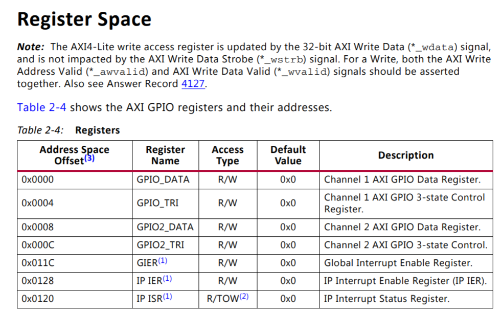
今回の設計ではGPIOは1チャネル、出力ポートのみの設定にしてあり、GPIO_DATAレジスタ値が出力ポートに反映されます。 GPIO_DATAのアドレスオフセットは0なので、これを引数としてwriteメソッドでレジスタ値を設定してLEDの点灯状態を変化させています。
レジスタアクセスの別の方法としてレジスタ名称を使用してアクセスすることもできます。
register_mapでレジスタ名称とレジスタの状態を参照できます。
print( ol.axi_gpio_0.register_map )
実行結果
RegisterMap {
  GPIO_DATA = Register(Channel_1_GPIO_DATA=1),
  GPIO_TRI = Register(Channel_1_GPIO_TRI=3),
  GPIO2_DATA = Register(Channel_2_GPIO_DATA=0),
  GPIO2_TRI = Register(Channel_2_GPIO_TRI=4294967295),
  GIER = Register(Global_Interrupt_Enable=1),
  IP_ISR = Register(Channel_1_Interrupt_Status=1, Channel_2_Interrupt_Status=0),
  IP_IER = Register(Channel_1_Interrupt_Enable=0, Channel_2_Interrupt_Enable=0)
}
これを使って以下のようにGPIO_DATAレジスタに値を設定できます。
ol.axi_gpio_0.register_map.GPIO_DATA = 3
PYNQではこれらレジスタなどIPの構成情報をビットストリームに対応するhwhファイルから取得してRegisterMapなどを生成するようです。
hwhの抜粋
<MODULES> <MODULE COREREVISION="24" FULLNAME="/axi_gpio_0" HWVERSION="2.0" INSTANCE="axi_gpio_0" IPTYPE="PERIPHERAL" IS_ENABLE="1" MODCLASS="PERIPHERAL" MODTYPE="axi_gpio" VLNV="xilinx.com:ip:axi_gpio:2.0"> <DOCUMENTS> <DOCUMENT SOURCE="http://www.xilinx.com/cgi-bin/docs/ipdoc?c=axi_gpio;v=v2_0;d=pg144-axi-gpio.pdf"/> </DOCUMENTS> <ADDRESSBLOCKS> <ADDRESSBLOCK ACCESS="read-write" INTERFACE="S_AXI" NAME="Reg" RANGE="4096" USAGE="register"> <REGISTERS> <REGISTER NAME="GPIO_DATA"> <PROPERTY NAME="DESCRIPTION" VALUE="Channel-1 AXI GPIO Data register"/> <PROPERTY NAME="ADDRESS_OFFSET" VALUE="0x0"/> <PROPERTY NAME="SIZE" VALUE="2"/> <PROPERTY NAME="ACCESS" VALUE="read-write"/> <PROPERTY NAME="IS_ENABLED" VALUE="true"/> <PROPERTY NAME="RESET_VALUE" VALUE="0x0"/> <FIELDS> <FIELD NAME="Channel_1_GPIO_DATA"> <PROPERTY NAME="DESCRIPTION" VALUE="AXI GPIO Data Register.
For each I/O bit programmed as input
 R - Reads value on the input pin.
 W - No effect.
For each I/O bit programmed as output
 R - Reads value on GPIO_O pins
 W - Writes value to the corresponding AXI GPIO 
 data register bit and output pin
"/> <PROPERTY NAME="ADDRESS_OFFSET" VALUE="0"/> <PROPERTY NAME="ACCESS" VALUE="read-write"/> <PROPERTY NAME="MODIFIED_READ_VALUES" VALUE=""/> <PROPERTY NAME="WRITE_CONSTRAINT" VALUE="0"/> <PROPERTY NAME="READ_ACTION" VALUE=""/> <PROPERTY NAME="BIT_OFFSET" VALUE="0"/> <PROPERTY NAME="BIT_WIDTH" VALUE="2"/> </FIELD> </FIELDS> </REGISTER>
まとめ
PYNQオーバーレイ作成として
- FPGA設計し、ビットストリームを作る
- PYNQ環境に1で生成したファイル群を配置し、Pythonで操作する
をやってみました。
今回FPGA設計部分はIPを並べて接続することしかやっていませんが一般的なハードウェアとしてのFPGA設計フローに沿ったものだろうと思います。 実用的な機能を実装するにはHDL記述や、C/C++記述と高位合成などを用いて機能ブロックの実装を行い、PSブロックとのインターフェースを設計する等のより細かなハードウェア設計が必要となりそうです。
オーバーレイの作成についてPYNQのドキュメントでは以下のように記載されています。
Project Goalsより抜粋
Creating a new overlay still requires engineers with expertise in designing programmable logic circuits.
Overlay Design Methodologyより抜粋
A software programmer can use an overlay, but will not usually create overlay, as this usually requires a high degree of hardware design expertise.
オーバーレイ開発はハードウェア設計の領域で通常はソフトウェア開発者が設計するものではないようですね。
このようにPYNQ環境はソフトウェア技術者だけでFPGAを使用するシステム全体の開発を行うことは難しそうですが、従来のシステム開発でFPGAなどのハードウェアをC言語などで開発したファームウェアで制御していた部分をPythonで行えればソフトウェア技術者も含め様々な技術者が開発しやすくなるのではないでしょうか。